Back to Kemp Acoustics Home


Next: Multimodal equations in a
Up: Multimodal propagation in acoustic
Previous: Plane waves in a
Contents
A wave experiences partial reflection and partial transmission at a change in
impedance. Such a change occurs at a change in cross-sectional area since the
characteristic impedance depends on  .
Consider the discontinuous join between two cylinders shown in
figure 2.2.
.
Consider the discontinuous join between two cylinders shown in
figure 2.2.
Figure 2.2:
Detail of a waveguide consisting of straight sections of length  joined discontinuously
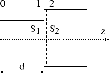 |
We label as plane 1 the cross-section with area  immediately to the left of the discontinuity.
Plane 2 is defined to be the cross-section with area
immediately to the left of the discontinuity.
Plane 2 is defined to be the cross-section with area  immediately to
the right. The pressure and volume velocity on either side of a change of
cross-section are equal, meaning that
immediately to
the right. The pressure and volume velocity on either side of a change of
cross-section are equal, meaning that
 and
and
 in the current notation. It follows that the acoustic
impedance is the same on each side of the discontinuity (ie.
in the current notation. It follows that the acoustic
impedance is the same on each side of the discontinuity (ie.
 ).
).
It should not seem strange that the acoustic
impedance is unaltered by the change in cross-section because the
characteristic impedance  has changed and the acoustic impedance
has therefore altered relative to the characteristic impedance.
We may use equation (2.13) to work out the impedance
at plane 0 and the effect of the new cross-section will then have an effect on
the resulting
has changed and the acoustic impedance
has therefore altered relative to the characteristic impedance.
We may use equation (2.13) to work out the impedance
at plane 0 and the effect of the new cross-section will then have an effect on
the resulting  value.
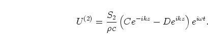
To further illustrate the point, we must deal with the forward and
backward going waves in each cylinder.
 and
and  are the complex pressure amplitudes for the waves
in the cylinder to the left of discontinuity, meaning the pressure
there from equation (2.2) is
are the complex pressure amplitudes for the waves
in the cylinder to the left of discontinuity, meaning the pressure
there from equation (2.2) is
 |
(2.14) |
 and
and  are the forward
and backward going complex pressure amplitudes in the cylinder on the right
of the discontinuity giving
are the forward
and backward going complex pressure amplitudes in the cylinder on the right
of the discontinuity giving
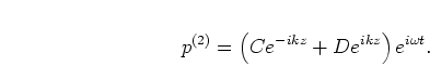 |
(2.15) |
Using
at the discontinuity (noting that planes 1 and
2 may be taken to be at the same  coordinate, just on opposite sides
of the infinitely sharp discontinuity) gives
coordinate, just on opposite sides
of the infinitely sharp discontinuity) gives
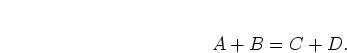 |
(2.16) |
From equation (2.7) the we volume velocity in plane 1 is
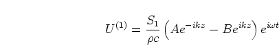 |
(2.17) |
and the volume velocity in plane 2 is
 |
(2.18) |
Using the
condition leads to
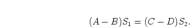 |
(2.19) |
While the sum of the forward and backward waves is the same on either side
of the discontinuity, the difference depends on the ratios of the
cross-sections, hence the waves experience reflection and transmission
coefficients.
In particular, consider if our pipes in figure 2.2 are infinite in
length. A pressure wave is
incident on the discontinuity from  with amplitude . It is
partially reflected with amplitude back down the tube to and
partially transmitted to
with amplitude . It is
partially reflected with amplitude back down the tube to and
partially transmitted to  with amplitude .
 since there is no backward going wave in . We can solve
(2.16) and (2.19) by eliminating
to get the reflection coefficient:
since there is no backward going wave in . We can solve
(2.16) and (2.19) by eliminating
to get the reflection coefficient:
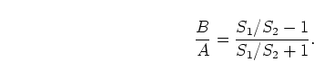 |
(2.20) |
A decrease in area means a positive reflection coefficient and an
increase in area means a negative reflection coefficient while there is no
reflection when  .
The transmission coefficient is obtained by eliminating in the same
equations:
.
The transmission coefficient is obtained by eliminating in the same
equations:
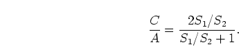 |
(2.21) |
To summarise, impedance is not effected by changes in cross-section
and equation (2.13) describes how impedance changes
when projected along a pipe of given cross-section.
Now we have the equations necessary to work out the impedance at one end of
a instrument of known internal profile provided the impedance at the other
end is known. The impedance at the open end will depend on the geometry of
the opening and is treated in detail in chapter 3. Projecting
the impedance down to the input (mouthpiece) end gives us the input impedance,
the amount of pressure produced in the mouthpiece by a unit
volume velocity source. Now we have derived a method of input impedance
calculation in the plane wave approximation, we will go on to do the same
for multimodal propagation.
Back to Kemp Acoustics Home
Next: Multimodal equations in a
Up: Multimodal propagation in acoustic
Previous: Plane waves in a
Contents
Jonathan Kemp
2003-03-24