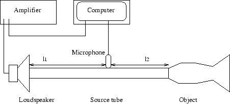
The computer sends out a 5 V electrical pulse of 80 ![]() s duration to an
audio amplifier.
A horn driver loudspeaker attached to the output then produces an acoustic
pulse (audible click) which travels down the air column of a cylindrical
source tube of internal radius 5 mm and then enters the object
to be measured. The complicated object reflections are then picked up by a
microphone in the side wall of the source tube and sampled by the computer
at a sample rate of
s duration to an
audio amplifier.
A horn driver loudspeaker attached to the output then produces an acoustic
pulse (audible click) which travels down the air column of a cylindrical
source tube of internal radius 5 mm and then enters the object
to be measured. The complicated object reflections are then picked up by a
microphone in the side wall of the source tube and sampled by the computer
at a sample rate of ![]() Hz.
This experiment is repeated 1000 times and the result averaged to increase the
signal to noise ratio. Length
Hz.
This experiment is repeated 1000 times and the result averaged to increase the
signal to noise ratio. Length ![]() is chosen so that the input pulse has completely passed the microphone before
the first reflections return from the object. The length
is chosen so that the input pulse has completely passed the microphone before
the first reflections return from the object. The length ![]() is ideally
chosen so that the
round trip time
is ideally
chosen so that the
round trip time ![]() is sufficient to record the full object
reflections without interference from reflections from the source.
This is of course dependent on the length of the instrument; longer
instruments have reflections which carry on for more time meaning that
a longer distance is required for
is sufficient to record the full object
reflections without interference from reflections from the source.
This is of course dependent on the length of the instrument; longer
instruments have reflections which carry on for more time meaning that
a longer distance is required for ![]() . The reflectometer used in this
chapter has lengths
. The reflectometer used in this
chapter has lengths ![]() m and
m and ![]() m.
m.