Back to Kemp Acoustics Home


Next: Experimental measurement of the
Up: Experimental measurement of the
Previous: Experimental measurement of the
Contents
The input impulse response of a system is defined as the reflections resulting
from excitation by an ideal acoustic impulse.
The acoustic pulse that is produced experimentally is not an ideal impulse
because of its finite duration. To get the input impulse response, we
need to deconvolve the pulse entering the object's input from the reflections
which return to the object's input. However, the measurement we make is of the
object reflections when they have experienced losses corresponding to travel
down the distance  back to the microphone. By terminating the source tube
in a flat plate or cap, we can give a 100
back to the microphone. By terminating the source tube
in a flat plate or cap, we can give a 100 reflection of the input pulse
down the same length of tube to the microphone. This measurement is
referred to as the calibration pulse.
reflection of the input pulse
down the same length of tube to the microphone. This measurement is
referred to as the calibration pulse.
The input impulse response at the input plane is the deconvolution of the
backward and forward going signals there. Our measurement records these
signals once they have travelled an extra distance of . In order to
recover the signals present at the input plane we could apply the same loss
filter to both. This corresponds to multiplying both by the same
function in the frequency domain. Since deconvolution is frequency domain
division, the effect of the loss filter will be divided out. The
input impulse response is therefore equal to the deconvolution of the
signals measured at the microphone:
 |
(5.29) |
where  is the Fourier transform of the calibration pressure pulse and
  is the Fourier transform of the reflected pressure signal.
  is a
constraining factor used to prevent division by zero which would otherwise
occur since the calibration pulse measurement consists only of background
noise at high frequencies. In practice it low pass filters the input
impulse response, removing high frequency noise. Choosing too large a value
for introduces errors into the deconvolution.
For the current set up,
is a
constraining factor used to prevent division by zero which would otherwise
occur since the calibration pulse measurement consists only of background
noise at high frequencies. In practice it low pass filters the input
impulse response, removing high frequency noise. Choosing too large a value
for introduces errors into the deconvolution.
For the current set up,  was found to remove much of the high
frequency noise, with a small change in having no effect
on the input impulse response within the bandwidth of our calibration pulse.
was found to remove much of the high
frequency noise, with a small change in having no effect
on the input impulse response within the bandwidth of our calibration pulse.
Figure 5.6 shows a measurement of the calibration pulse and
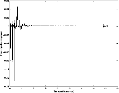
figure 5.7 shows the input impulse response resulting from the
deconvolution of the calibration pulse from the object reflections. The
characteristic shape of the calibration pulse has been removed from the object
reflections, making the individual reflections from the steps in the bore
impulsive as is expected.
Figure 5.6:
Calibration pulse
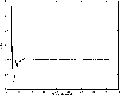 |
Figure 5.7:
Input impulse response
 |
Back to Kemp Acoustics Home
Next: Experimental measurement of the
Up: Experimental measurement of the
Previous: Experimental measurement of the
Contents
Jonathan Kemp
2003-03-24