Back to Kemp Acoustics Home next up previous contents
Next: Experimental measurement of the Up: Acoustic pulse reflectometry Previous: Experimental measurement of the   Contents


DC offset

The bore reconstruction is very sensitive to the dc offset since a small constant positive value will be interpreted by the bore reconstruction algorithm as a small positive reflection coefficient. For this reason Sharp et al. [19] placed a 40.3 cm long cylindrical connector with a radius of 4.8 mm (here referred to as the dc tube) between the source tube and the object. There will be no reflected signal from the dc tube (because there are no expansions and contractions) and the object reflections will arrive at the microphone 2 ms later because of the round trip time taken to travel in the dc tube. The average value of the input impulse response within the first 2 ms range may be subtracted from the whole input impulse response, so removing the dc offset.

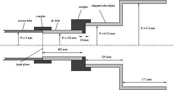
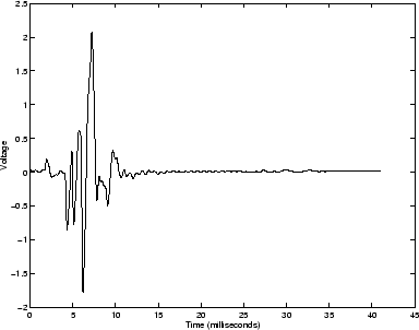
Figure 5.11 shows the reflections from the dc tube and stepped cylinder object. The reflections from the stepped cylinder object are preceded by the reflections from the join between the source tube and the dc tube. A schematic diagram of the test object attached to the source tube through the dc tube is shown in figure 5.10.

Figure 5.10: Stepped tube connected to source tube through dc tube
\begin{figure}\begin{center}
\epsfig{file=chapter5/steppedtubedc.eps,width=1\linewidth} \end{center}\end{figure}

Figure 5.11: Object reflections using dc tube
\begin{figure}\begin{center}
\epsfig{file=chapter5/stepdcms.eps,width=.70\linewidth} \end{center}\end{figure}

We can observe reflections from the stepped cylinder object are preceded by the reflections from the join between the source tube and the dc tube. This small reflection will also be present in the input impulse response. Ideally, this small bump in the internal profile would be perfectly reconstructed by the bore reconstruction algorithm. However, because the input impulse response is limited in frequency range, the impulsive reflection is spread out to make the pulse a small number of samples wide in the time domain. This means that the small leading edge occurs before the first sample. In accordance with signal processing theory, this small leading edge shows up in the last few samples in the time domain input impulse response. Errors result in the dc offset and bore reconstruction if this problem is ignored. The solution is to calculate the average value of the input impulse response between 1ms and 2ms and subtract this from the whole input impulse response. The response between 0ms and 1ms can then be replaced with zeros.


Back to Kemp Acoustics Home next up previous contents
Next: Experimental measurement of the Up: Acoustic pulse reflectometry Previous: Experimental measurement of the   Contents
Jonathan Kemp 2003-03-24