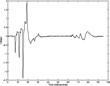
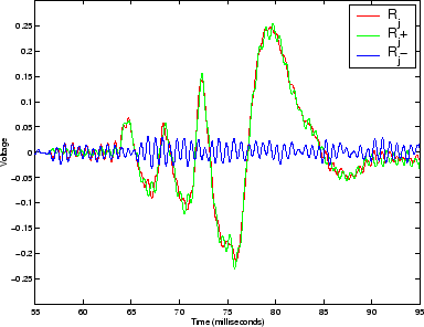
Figure 7.5 displays the second half of the object reflection
data, labelled ![]() . Also shown is
. Also shown is ![]() , the result of applying the
source reflection filter to give the forward travelling component of
, the result of applying the
source reflection filter to give the forward travelling component of ![]() ,
due to source reflections.
,
due to source reflections. ![]() is the result of subtracting
is the result of subtracting
![]() from
from ![]() to give the backward travelling component,
due to any remaining object reflections, with the source reflections
cancelled. As we expect for this
example, the data in the region shown consists entirely of source reflections
with
to give the backward travelling component,
due to any remaining object reflections, with the source reflections
cancelled. As we expect for this
example, the data in the region shown consists entirely of source reflections
with ![]() equal to zero, give or take a small amount of noise.
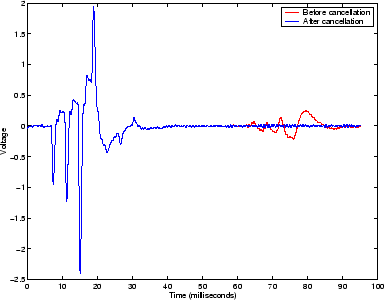
Figure 7.6 shows the full object reflection data, before and
after the cancellation of the source reflections.
The success of the post-processing subtraction of the source
reflections can be clearly seen.
equal to zero, give or take a small amount of noise.
Figure 7.6 shows the full object reflection data, before and
after the cancellation of the source reflections.
The success of the post-processing subtraction of the source
reflections can be clearly seen.
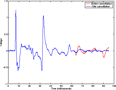
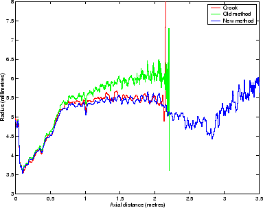
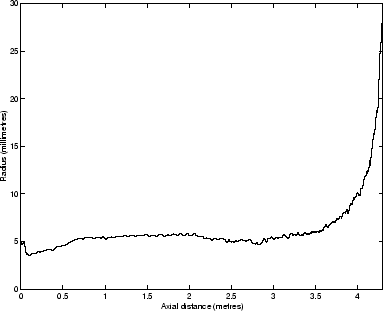
Figure 7.7 on the other hand shows the reflections from a French horn. The object reflections are too long to be separated in the time domain from the source reflections. Subtracting the source reflections is therefore vital if the response of the instrument is to be measured.
Figure 7.8 and figure 7.9 show bore reconstructions of the French Horn. Both use the virtual dc tube method. The line labelled ``Old method'' shows the reconstructed bore of a French horn using the pressure signal shown in figure 7.7 truncated just before the source reflections arrive. There is an upward trend in the bore reconstruction of a section of the pipe which is, in reality, cylindrical. The reconstruction is not accurate because the object reflections have not completely died out at this point. Also shown is a line labelled ``Crook,'' which shows the reconstructed bore of the detached crook (the section of tubing between the mouthpiece and the rest of the instrument). Since the crook section is short, the object and source reflections are separated in the pressure recording and, in this case, truncation of the signal gives an accurate reconstruction. The ``New method'' result uses the post processed version of the figure 7.7 object reflections with the source reflections removed.
The source reflection cancellation reconstruction of the French horn agrees with the reconstruction of the crook section showing that the technique enables longer objects to be measured accurately. While we have not verified that the remainder of the horn is reconstructed correctly (in fact there will still be errors due to higher mode propagation at the bell), it is clear that deviation has been greatly reduced.