Taking ![]() gives the radiation impedance of a square duct terminated
in an infinite baffle. It is interesting to compare this with the result
derived by Zorumski [37] for the radiation impedance for a circular
duct terminated in an infinite baffle.
The direct impedance of the plane wave mode (
gives the radiation impedance of a square duct terminated
in an infinite baffle. It is interesting to compare this with the result
derived by Zorumski [37] for the radiation impedance for a circular
duct terminated in an infinite baffle.
The direct impedance of the plane wave mode (![]() ,
, ![]() ) for
a square duct of half width
) for
a square duct of half width ![]() is shown in figure 3.5(a).
Also shown is the equivalent for a circular duct of the same cross-sectional
area (radius
is shown in figure 3.5(a).
Also shown is the equivalent for a circular duct of the same cross-sectional
area (radius
![]() ).
The results show very similar behaviour.
).
The results show very similar behaviour.
Figure 3.5(b) shows the impedance of the plane wave pressure mode
(![]() ) coupled with the
) coupled with the ![]() velocity mode for a square duct
of half width
velocity mode for a square duct
of half width ![]() along with the plane wave pressure mode coupled with the
pressure mode with two nodal circles in a cylindrical duct of the same
cross-sectional area. While the analogue between the two situations is less
strong, the same qualitative behaviour is observed.
along with the plane wave pressure mode coupled with the
pressure mode with two nodal circles in a cylindrical duct of the same
cross-sectional area. While the analogue between the two situations is less
strong, the same qualitative behaviour is observed.
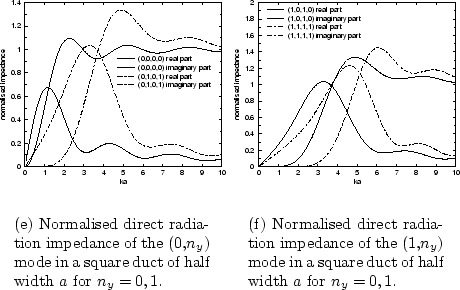
Figures 3.6(a) and 3.6(b) display various
direct radiation impedances for a square
duct. As was the case with circular cross-section, the radiation impedance
starts at zero for the zero frequency limit (as for the ideal open end
condition). At low frequencies the impedance has a small, positive imaginary
value. As with the circular cross-section discussion, this means that
the acoustic pressure has a node a small distance from the end of the tube
due to out of phase reflection of sound. At high frequencies the impedance
converges on the infinite cylindrical pipe termination value of 1
(or ![]() before normalisation). Modes with shorter transverse
wavelengths converge more slowly.
before normalisation). Modes with shorter transverse
wavelengths converge more slowly.
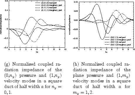
Figure 3.7(a) and 3.7(b) display coupled radiation impedances for a square duct. Figure 3.7(a) shows examples where the pressure and velocity are direct in one dimension and coupled in the other. Figure 3.7(b) shows examples where the pressure and velocity are coupled in both dimensions with a correspondingly smaller range of impedance values. As with the cylindrical geometry, the coupled radiation impedance and therefore the amount of inter-modal coupling tends to zero in both the zero frequency and high frequency limits.
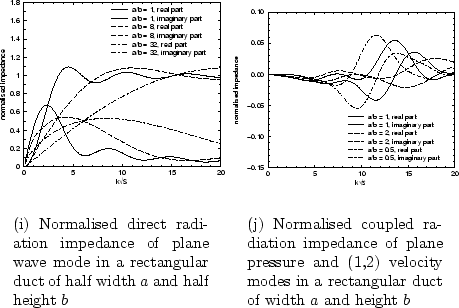
Figure 3.8(a) shows the effect of varying the aspect ratio (![]() ) on
the plane wave pressure and plane wave velocity radiation impedance. This
graph is in agreement with the values of the rectangular
piston radiation impedance as published by Burnett and Soroka [48].
Making the opening rectangular rather than square while keeping the
cross-sectional area constant is observed to make the direct impedance
of the plane mode converge much more slowly on the characteristic impedance
termination value. Physically this is a consequence of the opening having
one very narrow dimension, meaning that higher frequencies must be accessed
before the effects of diffraction at the opening disappear.
The direct impedance of the plane mode in a duct of a given aspect ratio
) on
the plane wave pressure and plane wave velocity radiation impedance. This
graph is in agreement with the values of the rectangular
piston radiation impedance as published by Burnett and Soroka [48].
Making the opening rectangular rather than square while keeping the
cross-sectional area constant is observed to make the direct impedance
of the plane mode converge much more slowly on the characteristic impedance
termination value. Physically this is a consequence of the opening having
one very narrow dimension, meaning that higher frequencies must be accessed
before the effects of diffraction at the opening disappear.
The direct impedance of the plane mode in a duct of a given aspect ratio
![]() will equal that of duct of aspect ratio
will equal that of duct of aspect ratio ![]() by symmetry.
This effect only holds if the pressure distribution has the same number of
nodal lines in both the
by symmetry.
This effect only holds if the pressure distribution has the same number of
nodal lines in both the ![]() and
and ![]() directions (ie.
directions (ie. ![]() ) and the
velocity distribution similarly has
) and the
velocity distribution similarly has ![]() .
.
Figure 3.8(b) shows the effect of aspect ratio on a coupled impedance.
The velocity distribution has twice as many nodes on the ![]() axis
as there are on the
axis
as there are on the ![]() axis while the pressure mode is planar.
The
axis while the pressure mode is planar.
The ![]() case shows the coupled impedance for a square duct.
Setting
case shows the coupled impedance for a square duct.
Setting ![]() , the duct width along
, the duct width along ![]() direction is half that
along
direction is half that
along ![]() . The transverse wavelength of the velocity distribution is
therefore four times as large along
. The transverse wavelength of the velocity distribution is
therefore four times as large along ![]() as along
as along ![]() .
The wavelength along one dimension is then very short, and we
observe that higher frequencies must be reached before coupling
takes place for the rectangular duct in comparison to a square duct of the
same area. For
.
The wavelength along one dimension is then very short, and we
observe that higher frequencies must be reached before coupling
takes place for the rectangular duct in comparison to a square duct of the
same area. For ![]() the duct is twice as wide
in the
the duct is twice as wide
in the ![]() direction meaning that the transverse wavelength is the same
along
direction meaning that the transverse wavelength is the same
along ![]() as along
as along ![]() .
In this this case we therefore observe that coupling with the plane
pressure mode can happen at lower frequencies for the rectangular duct.
.
In this this case we therefore observe that coupling with the plane
pressure mode can happen at lower frequencies for the rectangular duct.
![\begin{figure}\begin{center}
\subfigure[Normalised direct radiation impedance fo...
...]
{\epsfig{file=chapter3/z14b.eps,width=.41\linewidth}}
\end{center}\end{figure}](img432.png)